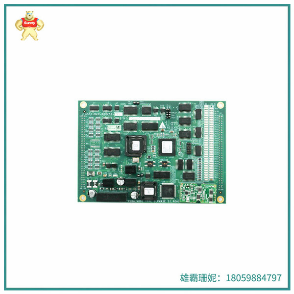
产品细节: 810-800256-015 LAM输入输出控制板模块PLC接收信号的端口
输入电路连接输入电路是PLC接收信号(一般为0-40MA直流电流或0-10V直流电压信号,用于模视)的端口,输入连接是指外部输入器件(任何无源触点和集电极打开的NPN三极管)通过输入电路闭合,同时输入指示发光二极管。810-800256-015常用的外部翰入设备包括按钮、接近开关、转换开关、dip开关、各种电感器等,它们是向系统发出各种控制信号的主要命令电器。
(1)PLC输入模块与主电气设备的连接
图中松下PLC为直流点输入,即这样输入点共用一个共同端子COM, COM瑞带DC24V电源,编写程序时要注意使用的外部设备是常闭触点还是常开触点。
输入端电气原理图中的停止按钮SEO使用串在控制线上的常闭触点进行关断控制。启动按HSB1,触点常开。810-800256-015设计中的两个梯形图实现了相同的控制功能,但停止信号XO使用不同的触点类型,因此连接端点的外部停止按钮触点类型不同。
/O分配s0-x0、s 1-x1,输出KO-YO。当外部使用长闭合触点时,不操作按钮,输出YO正常连接,在PLC控制系统中,外部开关无论启动或停止—般选择常开型。
⑵接近开关与PLC输入模块之间的连接在PLC控制系统设计中的布线工作比例很小,但它是编程设计的基础。为了保证接线工作正确,需要对PLC的输入输出电路有一个清晰的认识。
810-800256-015控制板的工作原理是通过传感器采集设备或系统的参数信息,如电压、电流、温度等,再将这些参数信息输入到控制算法中进行计算,最后将计算结果输出到驱动模块中,控制设备的运转状态。
例如电机控制器,其工作原理可以分为三个步骤:传感器采集、控制算法计算和输出驱动信号。首先电机控制器通过传感器采集电机的转速、转矩、电流等参数,然后将这些参数输入到控制算法中进行计算。控制算法根据电池组的电压、电流、温度等参数,以及驾驶员的操作指令,计算出电机的输出功率,并将输出功率转换为电机的控制信号,电机控制器将控制信号输出到驱动模块中,控制电机的转速和转矩。

Product Details: 810-800256-015 LAM Input/Output Control board module PLC receiving signal port
Input circuit connection The input circuit is the port of the PLC to receive the signal (generally 0-40MA DC current or 0-10V DC voltage signal, for mode vision), the input connection refers to the external input device (any passive contact and collector open NPN triode) closed through the input circuit, while the input indicating light emitting diode. 810-800256-015 Commonly used external input devices include buttons, proximity switches, transfer switches, dip switches, various inductors, etc., which are the main command appliances that send various air control signals to the system.
(1) Connection between PLC input module and main electrical equipment
The Panasonic PLC in the figure is a DC point input, that is, the input point shares a common terminal COM, COM with DC24V power supply, when writing programs, pay attention to the use of external equipment is normally closed contact or normally open contact.
The stop button in the input electrical schematic SEO uses a normally closed contact strung on the control line for shutdown control. Press HSB1 to start, contact is always open. The two trapezoids in the 810-800256-015 design achieve the same control function, but the stop signal XO uses different contact types, so the external stop button contact types for the connecting endpoints are different.
/O allocates s0-x0, s1-x1, and outputs KO-YO. When the long closed contact is used externally, the button is not operated, and the output YO is connected normally. In the PLC control system, the external switch is started or stopped - normally open type is generally selected.
(2) The connection between the proximity switch and the PLC input module is very small in the wiring work proportion of the PLC control system design, but it is the basis of programming design. In order to ensure that the wiring works correctly, it is necessary to have a clear understanding of the input and output circuits of the PLC.
810-800256-015 The working principle of the control board is to collect the parameter information of the device or system through the sensor, such as voltage, current, temperature, etc., and then input these parameter information into the control algorithm for calculation, and finally output the calculation results to the drive module to control the operating state of the device.
For example, the motor controller, its working principle can be divided into three steps: sensor acquisition, control algorithm calculation and output drive signal. First, the motor controller collects the motor speed, torque, current and other parameters through the sensor, and then input these parameters into the control algorithm for calculation. The control algorithm calculates the output power of the motor according to the battery's voltage, current, temperature and other parameters, as well as the driver's operating instructions, and converts the output power into the control signal of the motor, and the motor controller outputs the control signal to the drive module to control the speed and torque of the motor.

| TRICONEX | 8312 | TRICONEX | 8312 |
| TRICONEX | 3604E | TRICONEX | 3664 |
| TRICONEX | 3721 | TRICONEX | 3625 |
| TRICONEX | 3503E | TRICONEX | 3503E |
| TRICONEX | 3623T | TRICONEX | 3700A |
| TRICONEX | 3720 | TRICONEX | 3805E |
| HONEYWELL | 05701-A-0302 | ENTERASYS | A2H254-16 |
| HONEYWELL | CC-TCNT01 | ENTERASYS | P0973BK |
Copyright © 2022-2024 厦门雄霸电子商务有限公司 版权所有 备案号:闽ICP备14012685号-33