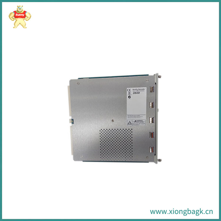
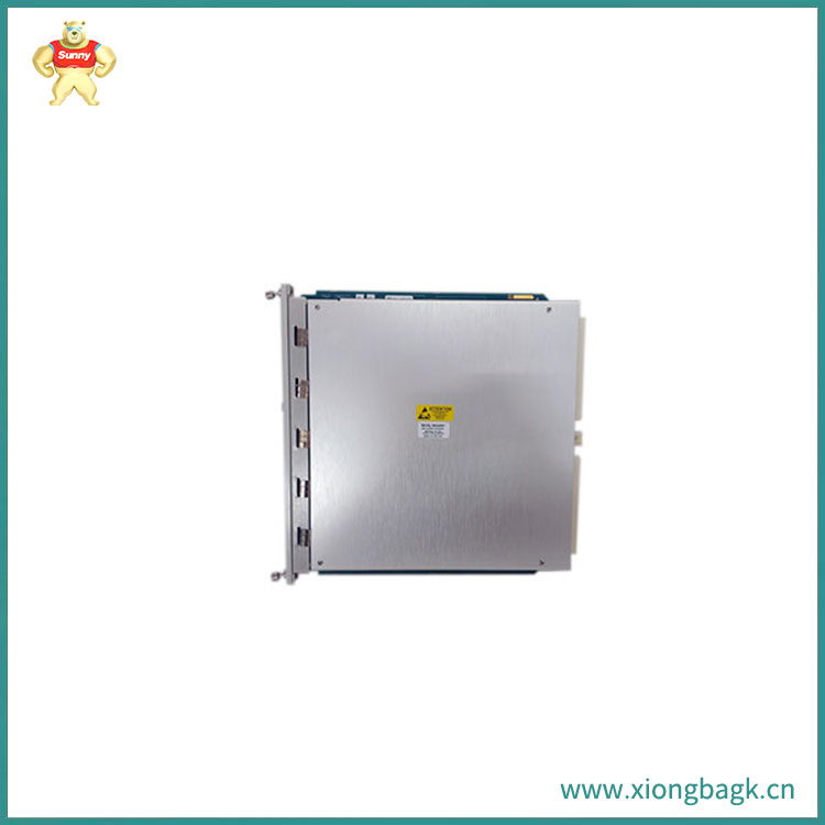
3500/22M是由本特利内华达开发的瞬态数据接口模块。它用作与 3500 监测系统兼容的软件接口(系统 1 状态监测和诊断软件以及 3500 系统配置软件)。TDI 将 3500/20 机架接口模块 (RIM功能) 与通信处理器(如 TDXnet)相结合,以收集数据。
它用于在“运行”和“程序”模式之间切换 3500 机架。RUN 模式可防止配置修改,同时允许机架正常运行。机架可以在本地或远程配置,同时在程序模式下仍正常运行。交换机可以保持在运行或编程位置,方法是从机架中取出任一位置的密钥。您可以通过将交换机锁定在 RUN 位置来防止不必要的机架重新配置。每当需要远程重新配置机架时,交换机都可以锁定在 PROGRAM 位置。
用于将信号公共连接到机架的单点仪器接地的 2 针连接器现在在两个版本的 TDI I/O 模块中都有。要在执行此操作后将共模信号与机箱(安全)接地隔离,请向“HP”箭头方向滑动电源输入模块 (PIM) 侧的选择器开关。
BN 主机协议通信中的 BN 主机协议
3500 配置软件、3500 数据采集软件和 3500 显示软件
BN TDI 协议系统 1 状态监测和诊断软件以及 BN TDI 协议


The 3500/22M is a transient data interface module developed by Bentley Nevada. It is used as a software interface compatible with the 3500 monitoring system (System 1 status monitoring and diagnostic software, as well as the 3500 system configuration software). TDI combines the 3500/20 Rack Interface Module (RIM function) with communication processors such as TDXnet to collect data.
3500/22M Function
In a 3500 rack, the TDI is located in the slot next to the power supply. In order to continuously collect steady-state and transient dynamic (waveform) data and transmit it to the host software through an Ethernet link, it interacts with M-series monitors (3500/40M, 3500/42M, etc.).
TDI has traditional static data collection capabilities. However, TDI can also use optional channels to enable disk recording of dynamic, high-resolution transient data.
Function Description
The 3500 rack accommodates the communication processing functions of TDI. Although TDI performs tasks shared by the entire rack, it is not a critical component of the monitoring system and is independent of the degree to which the entire system monitors autonomous mechanical protection.
Each 3500 rack requires one TDI or RIM and always occupies slot 1. (next to the power supply).
The link between the 3500 monitoring system and compatible software is called the 3500/22M Transient Data Interface (TDI) (System 1 Status Monitoring and Diagnostic Software and 3500 System Configuration Software). TDI combines the 3500/20 Rack Interface Module (RIM function) with communication processors such as TDXnet to collect data.
position
In a 3500 rack, the TDI is located in the slot next to the power supply. In order to continuously collect steady-state and transient dynamic (waveform) data and transmit it to the host software through an Ethernet link, it interacts with M-series monitors (3500/40M, 3500/42M, etc.). TDI has traditional static data collection capabilities. However, TDI can also use optional channels to enable disk recording of dynamic, high-resolution transient data.
The 3500 rack accommodates the communication processing functions of TDI. Although TDI performs tasks shared by the entire rack, it is not a critical component of the monitoring system and is independent of the degree to which the entire system monitors autonomous mechanical protection.
Each 3500 rack requires one TDI or RIM and always occupies slot 1. (next to the power supply).
Configure keylock
It is used to switch 3500 racks between "Run" and "Program" modes. The RUN mode prevents configuration modifications while allowing the rack to operate normally. The rack can be configured locally or remotely, while still operating normally in program mode. The switch can be kept in the running or programming position by removing the key from any position in the rack. You can prevent unnecessary rack reconfiguration by locking the switch in the RUN position. Whenever it is necessary to remotely reconfigure the rack, the switch can be locked in the Program position.
I/O module signal common terminal
The 2-pin connector for connecting the signal to the single point instrument ground of the rack is now available in both versions of the TDI I/O module. To isolate the common mode signal from the chassis (safety) ground after performing this operation, slide the selector switch on the power input module (PIM) side towards the "HP" arrow.
data acquisition
Keyphase input
Supports four key signals for the 3500 system.
The number of active dynamic channels determines the speed range support.
Supports speed input, with multiple occurrences per rotation, up to 20 kHz.
Starting/taxiing data
Data collected at predetermined speeds and time intervals; Separately programmed increase and decrease intervals.
After detecting the speed of the machine within one of the two programmable windows, transient data collection will begin.
The memory capacity of a module is the only limit on the number of temporary events that can be collected.
Alarm data collection
Collect 5.10 minutes of waveform data at 2-second intervals before the alarm, and 10 minutes of waveform data at 1-second intervals after the alarm.
Pre alarm and post alarm data.
Static values collected at one second intervals between 10 minutes before and 1 minute after the event.
Static values collected at intervals of 100 milliseconds, 20 seconds before and 10 seconds after the event.
Static value data
Static values (including those determined by the monitor) will be collected by TDI.
For each point, l TDI provides four nX static values. For each value, return the amplitude and phase.
signal communication
BN Host Protocol in BN Host Protocol Communication
3500 configuration software, 3500 data acquisition software, and 3500 display software
BN TDI Protocol System 1 Status Monitoring and Diagnostic Software and BN TDI Protocol
Copyright © 2022-2024 厦门雄霸电子商务有限公司 版权所有 备案号:闽ICP备14012685号-33