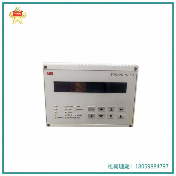
型号:SYN5200a-Z,V217 SYNCHROTACT5 3BHB006713R0217
品牌:ABB
制造商:ABB
系列:控制系统
产品描述
SYN5200a-Z,V217 SYNCHROTACT5 3BHB006713R0217 ABB是SYNCHROTACT 5数字同步器用于自动同步和发电机与线路的并联以及已同步线路的并联。该设备设计用于50/60 Hz或162/3 Hz的系统频率。
SYN 5200由两个具有不同硬件和软件的独立通道组成。这种双通道特性最大限度地提高了防止错误并联的安全性。并联所需的所有参数都存储在一个参数集中。并联电压和频率匹配器的条件和特性在这套。通过提供七个参数集的选项,可以进行并联在不同的条件下或使用相同的匹配器具有不同的匹配器特性装置七个可配置的数字输入和输出可供选择参数集的反向指示。
对于调试和控制而言非常重要的数据可以是使用电脑工具SynView上传或下载,或者通过单元的前面板。
自动并联过程基本上可分为四个功能块:
1.测量
2.电压和频率匹配
3.并联状态监测
4.并行命令生成
电压测量
两个输入电压U1和U2通过高阻抗输入传递到处理器、电阻器、差分放大器、低通滤波器和AD转换器。
电压测量通道2
两个输入电压U1和U2通过高阻抗输入电阻器以及差动放大器。振幅值的信号由以下公式形成转换和过滤。对于过零检测,信号经过滤波并通过通过比较器。以这种方式准备的信号通过A/D转换器。
电压和频率匹配
电压匹配器的工作范围如果电压U1在Umin和Umax之间的范围内,并且电压U2更大大于U0max,则释放调节命令。调整的方向。
命令取决于AU的极性。
作为附加条件,两个频率必须在fn+5 Hz的范围内。

Model: SYN5200a-Z, V217 SYNCHROTACT5 3BHB006713R0217
Brand :ABB
Manufacturer: ABB
Series: Control systems
Product description
SYN5200a-Z, V217 SYNCHROTACT5 3BHB006713R0217 ABB is a SYNCHROTACT5 digital synchronizer for automatic synchronization and parallel operation of generators and lines, as well as parallel operation of synchronized lines. The device is designed for system frequencies of 50/60 Hz or 162/3 Hz.
SYN 5200 consists of two separate channels with different hardware and software. This two-channel feature maximizes security against parallel errors. All parameters required for parallel connection are stored in one parameter set. Conditions and characteristics of parallel voltage and frequency matchers in this set. By providing the option of seven parameter sets, seven configurable digital inputs and outputs can be selected for the reverse indication of parameter sets that can be performed in parallel under different conditions or devices with different matcher characteristics using the same matching appliance.
Data that is important for debugging and control can be uploaded or downloaded using the computer tool SynView, or via the front panel of the unit.
The automatic parallel process can be basically divided into four functional blocks:
Step 1 Measure
2. Voltage and frequency matching
3. Parallel status monitoring
4. Generate parallel commands
Voltage measurement
The two input voltages U1 and U2 are passed through the high-impedance input to the processor, resistor, differential amplifier, low-pass filter, and AD converter.
Voltage measurement channel 2
Two input voltages U1 and U2 pass through a high-impedance input resistor as well as a differential amplifier. The amplitude values of the signal are converted and filtered by the following formula. For zero-crossing detection, the signal is filtered and passed through the comparator. In this way the signal is prepared through A/D converter.
Voltage and frequency matching
Voltage matcher operating range If the voltage U1 is in the range between Umin and Umax and the voltage U2 is greater than U0max, release the regulation command. Adjust the direction.
The command depends on the polarity of the AU.
As an additional condition, both frequencies must be in the fn+5 Hz range.

| EMERSON | CE3008 | VIBRO-METER | VM600 |
| EMERSON | KJ2005X1-MQ1 | VIBRO-METER | VM600 |
| EMERSON | 12P6381X042 | VIBRO-METER | VM600 |
| EMERSON | CON021 | DEIF | DLQW72-PC-PY |
| EMERSON | 38B5786X132 | DUNKERMOTOREN | BG65X50SI |
| EMERSON | KJ3002X1-BF1 | DEIF | VTR-5-PY |
| EMERSON | 1C31222G01 | VTR-5-PY | 3500/22M 288055-01 |
| EMERSON | MVME7100 | PROSOFT | MVI94-MCM-MHI |
| EMERSON | 9199-00002 A6120 | KONGSBERG | DPS112 |
Copyright © 2022-2024 厦门雄霸电子商务有限公司 版权所有 备案号:闽ICP备14012685号-33