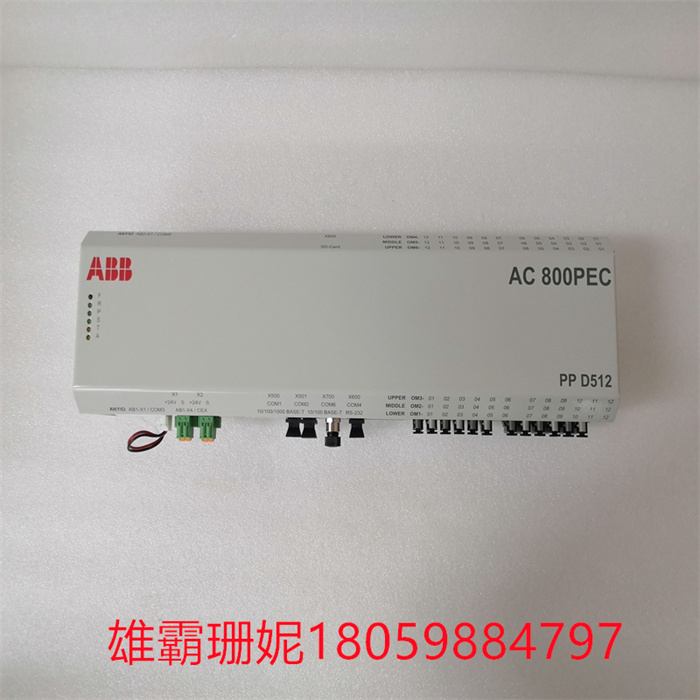
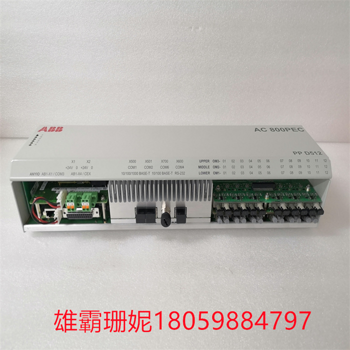
PPD512A10-150000 ABB 逻辑控制模块

在用户程序执行阶段,PLC总是按由 上而下的顺序依次地扫描用户程序(梯形图)。在扫描每一条梯形图时, 又总是先扫描梯形图左边的由各触点构成的控制线路,并按先左后右、先上后下的顺序对由触点构成的控制线路进行逻辑运算,然后根据逻辑运算的结果,刷新该逻辑线圈在系统RAM存储区中对应位的状态;或者刷新该输出线圈在I/O映象区中对应位的状态;或者确定是否要执行该梯形图所规定的特殊功能指令。即,在用户程序执行过程中,只有输入点在I/O映象区内的状态和数据不会发生变化,而其他输出点和软设备在I/O映象区或系统RA存储区内的状态和数据都有可能发生变化,而且排在上面的梯形图,其程序执行结果会对排在下面的凡是用到这些线圈或数据的梯形图起作用;相反,排在下面的梯形图,其被刷新的逻辑线圈的状态或数据只能到下一个扫描周期才能对排在其上面的程序起作用。
PLC是采用"顺序扫描,不断循环”的方式进行工作的。即在PLC运行时,CPU根据用户按控制要求编制好并存于用户存储器中的程序,按指令步号(或地址号)作周期性循环扫描,如无跳转指令,则从条指令开始逐条顺序执行用户程序,直至程序结束。然后重新返回条指令,开始下一轮新的扫描。在每次扫描过程中,还要完成对输入信号的采样和对输出状态的刷新等工作。PLC的一个扫描周期必经输入采样、程序执行和输出刷新三个阶段。PLC在输入采样阶段:首先以扫描方式按顺序将所有暂存在输入锁存器中的输入端子的通断状态或输入数据读入,并将写入各对应的输入状态寄存器中,即刷新输入。随即关闭输入端口,进入程序执行阶。PLC在程序执行阶段:按用户程序指令存放的先后顺序扫描执行每条指令,经相应的运算和处理后,其结果再写入输出状态寄存器中,输出状态寄存器中所有的内容随着程序的执行而改变。输出刷新阶段:当所有指令执行完毕,输出状态寄存器的通断状态在输出刷新阶段送至输出锁存器中,并通过一定的式(继电器、晶体管或晶闸管)输出,驱动相应输出设备工作。PLC的工作过程,PLC的运行方式初研制生产的PLC主要用于代替传统的由继电器接触器构成的控制装置,但这两者的运行方式是不相同的:
(1)继电器控制装置采用硬逻辑并行运行的方式,即如果这个继电器的线圈通电或断电,该继电器所有的触点(包括其常开或常闭触点)在继电器控制线路的哪个位置上都会立即同时动作。
(2)PLC的CPU则采用顺序逻辑扫描用户程序的运行方式,即如果一个输出线圈或逻辑线圈被接通或断开,该线圈的所有触点(包括其常开或常闭触点)不会立即动作,必须等扫描到该触点时才会动作。为了消除二者之间由于运行方式不同而造成的差异,考虑到继电器控制装置各类触点的动作时间一般在100ms以上,而PLC扫描用户程序的时间一般均小于100ms,因此,PLC采用了 -种不同于一般微型计 算机的运行方式扫描技术。这样在对于I/O响应要求不高的场合, PLC 与继电器控制装置的处理结果上就没有什么区别了。
PPD512A10-150000 ABB 逻辑控制模块

In the user program execution stage, PLC always scans the user program (ladder diagram) in order from top to bottom. When scanning each ladder diagram, always scan the control circuit composed of contacts on the left side of the ladder diagram first, and perform logical operation on the control circuit composed of contacts in the order of first left and then right, first up and then down, and then refresh the state of the corresponding bit of the logic coil in the system RAM storage area according to the result of logical operation; Or refresh that state of the corresponding bit of the output coil in the I/O map area; Or determine whether to execute the special function instruction specified in the ladder diagram. That is, in the process of user program execution, only the state and data of the input point in the I/O image area will not change, while the state and data of other output points and soft devices in the I/O image area or the system RA storage area may change, and the program execution result of the ladder diagram ranked above will play a role in the ladder diagram ranked below that uses these coils or data; On the contrary, in the ladder diagram arranged below, the status or data of the refreshed logic coil can only work on the program arranged above it in the next scanning cycle.
PLC works in a way of "sequential scanning and continuous circulation". That is, when the PLC is running, the CPU periodically scans the program stored in the user's memory according to the user's control requirements according to the instruction step number (or address number). If there is no jump instruction, the user's program will be executed one by one from the instruction until the program ends. Then return to instructions and start the next round of new scanning. In each scanning process, it is necessary to sample the input signal and refresh the output state. A scanning cycle of PLC must go through three stages: input sampling, program execution and output refresh. In the input sampling stage of PLC, firstly, the on-off state or input data of all the input terminals temporarily stored in the input latch are read in sequence by scanning mode, and will be written into each corresponding input state register, that is, the input is refreshed. Then close the input port and enter the program execution stage. In the program execution stage, PLC scans and executes each instruction according to the sequence in which the user's program instructions are stored. After corresponding operation and processing, the result is written into the output status register, and all the contents in the output status register change with the execution of the program. Output refresh stage: when all instructions are executed, the on-off state of the output status register is sent to the output latch in the output refresh stage, and it is output through a certain formula (relay, transistor or thyristor) to drive the corresponding output equipment to work. The working process and operation mode of PLC PLC is mainly used to replace the traditional control device composed of relay contactors, but the operation modes of the two are different:
(1) The relay control device operates in parallel with hard logic, that is, if the coil of the relay is powered on or off, all contacts of the relay (including its normally open or normally closed contacts) will act at the same time at any position on the relay control line.
(2) The CPU of 2)PLC adopts the operation mode of sequential logic scanning user program, that is, if an output coil or logic coil is turned on or off, all contacts of the coil (including its normally open or normally closed contacts) will not act immediately, and will only act when the contact is scanned. In order to eliminate the difference caused by different operation modes between them, considering that the action time of various contacts of relay control devices is generally more than 100ms, and the time for PLC to scan user programs is generally less than 100ms, therefore, PLC adopts a scanning technology of operation modes different from that of general microcomputers. In this way, there is no difference in the processing results between PLC and relay control device when I/O response is not high.


Copyright © 2022-2024 厦门雄霸电子商务有限公司 版权所有 备案号:闽ICP备14012685号-33