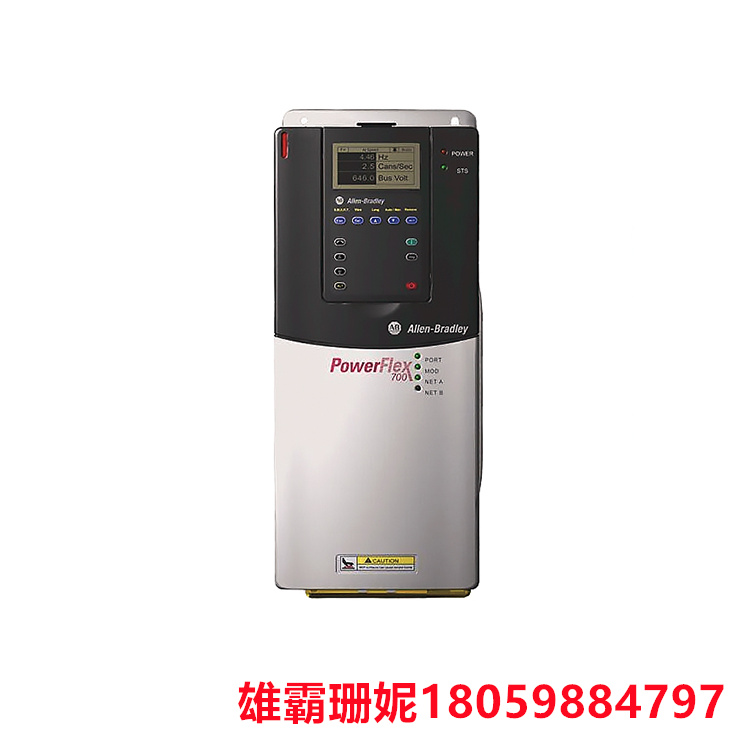
20BD248A0ANNANC0是一款Allen-Bradley可调频率交流驱动器。该变频器是 PowerFlex 700 的一部分,可在 380-480 伏交流电的三相输入电压下运行。它提供 0-460 伏交流电的输出电压,三相;适用电机输出功率为正常运载时200马力,重载运转时150马力;连续输出电流为 248 安培。该20BD248A0ANNANC0驱动器安装在提供 IP20/IP00、NEMA/UL Type 1 级外壳的外壳上。它配备了一个集成的IGBT制动器和一个内部交流线路滤波器,并增加了矢量控制功能。它没有通信模块、编码器反馈和人机接口模块 (HIM)。
可调变频器是一种用于调节电机转速的电子设备。它通过改变电机输入电源的频率和电压来控制电机的转速。

编号:20BD248A0ANNANC0
修订版:Ser A
描述: 20BD248A0ANNANC0是一款Allen-Bradley可调频率交流驱动器。该变频器是 PowerFlex 700 的一部分,可在 380-480 伏交流电的三相输入电压下运行。它提供 0-460 伏交流电的输出电压,三相;适用电机输出功率为正常运载时200马力,重载运转时150马力;连续输出电流为 248 安培。该20BD248A0ANNANC0驱动器安装在提供 IP20/IP00、NEMA/UL Type 1 级外壳的外壳上。它配备了一个集成的IGBT制动器和一个内部交流线路滤波器,并增加了矢量控制功能。它没有通信模块、编码器反馈和人机接口模块 (HIM)。
可调变频器是一种用于调节电机转速的电子设备。它通过改变电机输入电源的频率和电压来控制电机的转速。
20BD248A0ANNANC0可调变频器通常由控制器、功率放大器、编码器、传感器等组成。控制器可以接收外部的控制信号,并根据信号的要求生成电机的控制信号。功率放大器是用于放大控制器输出的控制信号,以驱动电机运行。编码器是用于检测电机的位置和速度,并将这些信息反馈给控制器,以实现位置和速度的闭环控制。传感器是用于检测电机的运行状态,如温度、电流、电压等,以确保电机的安全运行。
20BD248A0ANNANC0可调变频器广泛应用于各种自动化设备和机器人中,如机床、印刷机、包装机、工业机器人等。它们能够提供高精度、高速度和高效率的运动控制,提高了生产效率和产品质量。
使用可调变频器的步骤如下:
1. 选择合适的变频器:根据电机的类型、功率、电压等参数选择合适的变频器。
2. 连接变频器:20BD248A0ANNANC0将变频器连接到电机和电源上,并确保连接正确。
3. 配置变频器参数:根据电机的参数和控制要求,配置变频器的参数,如电机类型、功率、转速、加速度、位置控制模式等。
4. 调试变频器:20BD248A0ANNANC0在变频器连接好电机和编码器后,进行调试。可以通过手动操作或使用自动调试工具来检查电机的运行状态和变频器的控制效果。
5. 调整变频器参数:20BD248A0ANNANC0根据实际的运行情况,调整变频器的参数,以获得更好的控制效果。
6. 测试变频器:在完成调试和调整后,进行测试以确保变频器和电机的正常运行。
需要注意的是,在使用可调变频器时,应该遵循相关的安全规定和操作规程,以确保人员和设备的安全。同时,应该根据实际情况选择合适的工具和方法,以提高工作效率和质量。

Number: 20BD248A0ANNANC0
Revised Edition: Ser A
Description: The 20BD248A0ANNANC0 is an Allen-Bradley adjustable frequency AC driver. The inverter is part of the PowerFlex 700 and operates at a three-phase input voltage of 380-480 volts AC. It provides 0-460 AC output voltage, three phases; The output power of the motor is 200 HP during normal load and 150 HP during heavy load operation. The continuous output current is 248 amps. The 20BD248A0ANNANC0 driver is mounted on a housing that provides IP20/IP00, NEMA/UL Type 1 housing. It is equipped with an integrated IGBT brake and an internal AC line filter, and adds vector control functions. It has no communication module, encoder feedback and human Machine interface module (HIM).
A variable frequency converter is an electronic device used to adjust the speed of a motor. It controls the speed of the motor by changing the frequency and voltage of the input power to the motor.
20BD248A0ANNANC0 Adjustable frequency converter is usually composed of a controller, a power amplifier, an encoder, a sensor, etc. The controller can receive external control signals and generate motor control signals according to the requirements of the signals. The power amplifier is used to amplify the control signal output by the controller to drive the motor operation. The encoder is used to detect the position and speed of the motor and feed this information back to the controller to achieve closed-loop control of the position and speed. Sensors are used to detect the operating state of the motor, such as temperature, current, voltage, etc., to ensure the safe operation of the motor.
20BD248A0ANNANC0 Adjustable inverter is widely used in a variety of automation equipment and robots, such as machine tools, printing presses, packaging machines, industrial robots and so on. They provide high precision, high speed and efficient motion control, improving production efficiency and product quality.
The steps to use the adjustable inverter are as follows:
1. Select the right inverter: Select the right inverter according to the type of motor, power, voltage and other parameters.
2. Connect the frequency converter: 20BD248A0ANNANC0 Connect the frequency converter to the motor and power supply, and ensure that the connection is correct.
3. Configure frequency converter parameters: According to the parameters and control requirements of the motor, configure the parameters of the frequency converter, such as motor type, power, speed, acceleration, position control mode, etc.
4. Commissioning the inverter: 20BD248A0ANNANC0 After the inverter is connected to the motor and the encoder, commissioning is carried out. The running state of the motor and the control effect of the inverter can be checked by manual operation or by using automatic debugging tools.
5. Adjust the parameters of the inverter: 20BD248A0ANNANC0 According to the actual operation, adjust the parameters of the inverter to obtain better control effect.
6. Test inverter: After debugging and adjustment, test to ensure the normal operation of inverter and motor.
It should be noted that when using the adjustable frequency converter, the relevant safety regulations and operating procedures should be followed to ensure the safety of personnel and equipment. At the same time, appropriate tools and methods should be selected according to the actual situation to improve work efficiency and quality.

| 1C31129G03 | ABB DSPC 452 | 8440-1666 | DSQC633B |
| 1X00416H01 | ABB DSTC 452 | 8440-1667 | DSQC662 |
| 2N3A8204-B | ABB PFSK 103 | 8440-1668 | DSQC1000 |
| 3ASC25H203 | DSAI 130D | 8440-1705 | DSQC1015 |
| 3ASC25H209 | DSAI 301 | 8440-1706 | DSTD1015DSTA 150A 57160001-UH |
| 3ASC25H214 | DSPC 320 | 8440-1715 | SDCS POW 4 SD |
| 3HNA024871-001 | DSPC 454 | 8440-1750 | 3BDH000368R0001-CM-772F |
| 5SHX08F4502 | 531X184IPTAEG1 | 8440-1751 | 3BDH001001R0001-PM-901F |
| 5SHX0660F0002 | 531X184IPTAFG1 | 8440-1798 | 3BHB007445P0001 |
| 5SHX1060H0003 | 531X185CPTAKG1 | 8440-1799 | 3BHE006373R0101,-XV-C769-AE101 |
| 5SHX1445H0002 | 531X185CPTALG1 | 8440-1800 | 3BHE014023R0101,-UF-C789-AE101 |
| 5SHY3545L0016 | 531X185CPTAMG1 | 8440-1801 | 3BHL000629P1005 |
Copyright © 2022-2024 厦门雄霸电子商务有限公司 版权所有 备案号:闽ICP备14012685号-33