全国咨询热线
全国咨询热线

1336-BDB-SP72D
制造者:罗克韦尔自动化
品牌:艾伦-布拉德利
型号:1336-BDB-SP72D
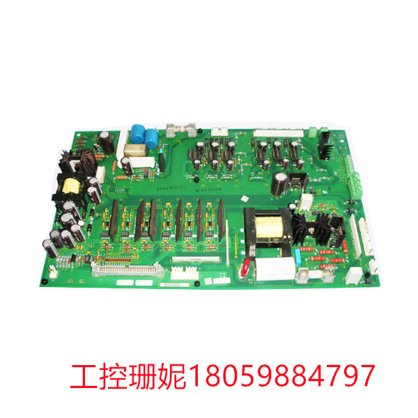
描述:印刷电路板栅极驱动板
1336-BDB-SP72D栅极驱动板是一种用于放大来自微控制器或其他来源的低电压或低电流的缓冲电栅极驱动板。
栅极驱动板可以控制功率开关的导通和关断,保护功率开关免受过电压、过电流等故障情况的影响,同时也可以提供故障诊断及故障信息等功能。
栅极驱动板广泛应用于工业机械、自动化系统、交通运输和家用电器等领域。
印刷电路板栅极驱动板的作用是控制场效应管的导通和截止。
1336-BDB-SP72D栅极驱动电路通常由一个信号源和一个驱动电路组成。信号源可以是一个电压源、一个信号发生器或一个传感器。驱动电路通常由一个放大器和一个输出级组成。放大器的作用是将信号源的信号放大到足以控制场效应管的电压水平。输出级的作用是将放大器的输出信号转换为适当的电压和电流,以控制场效应管的栅极电压。
描述: Allen-Bradley的1336-BDB-SP72D是PCB栅极驱动板系列的—部分,专为与可调频率交流驱动器配合使用而设计。该板能够在460VAC电压下运行,并且还具有250HP的额定马力。该板具有多个模块,每个模块都能够有效地适应框架尺寸A、B、C、D或E。1336-BDB-SP72D板具有制动斩波器模块,需要以正确的方式安装,以便提供最佳性能。
关于1336-BDB-SP72D
Allen-Bradley 的133-BDB-SP72D是PCB栅极驱动板系列的一部分,专为与可调频率交流驱动器配合使用而设计。该板能够在46NVAC电压下运行,并且还具有250HP的额定马力。该板具有多个模块,每个模块都能够有效地适应框架尺寸A、B、C、D或E。133-BDB-SP72D板具有制动斯波器模块,需要以正确的方式安装,以便提供最佳性能。需要牢记的第一个基本指令是将制动斩波器安装在垂直位置,因为这至关重要,然后可以遵循所有其他说明。
安装152-BDB-SP4D板的制动斯波器时,制动j斩波器模块之间的最小间隙应为1336.72mm。有问题的制动模块是外壳内的制励模块。然后,制动电阻组应安装在外壳外部的不然表面上。如果制时斩波器需要多个模块,则需雯将所有模块安装在距离斩波器模块10英尺(3米)以内的位置。剩余的所有其他存储模块必须由用户确定。还应确定每个电阻组之间的最小距离,因为它们都取决于应用。
1336-BDB-SP72D
Manufacturer: Rockwell Automation
Brand: Alan Bradley
Model :1336-BDB-SP72D
Description: Printed circuit board gate driver board
The 1336-BDB-SP72D gate driver board is a buffer electric gate driver board used to amplify low voltage or low current from a microcontroller or other source.
The grid driver board can control the power switch on and off, protect the power switch from overvoltage, overcurrent and other fault conditions, and also provide fault diagnosis and fault information.
Grid drive plates are widely used in industrial machinery, automation systems, transportation and household appliances.
The function of the grid driver board of the printed circuit board is to control the conduction and cutoff of the FET.
The 1336-BDB-SP72D gate driver circuit usually consists of a signal source and a driver circuit. The signal source can be a voltage source, a signal generator, or a sensor. The drive circuit usually consists of an amplifier and an output stage. The role of the amplifier is to amplify the signal from the signal source enough to control the voltage level of the FET. The role of the output stage is to convert the output signal of the amplifier into the appropriate voltage and current to control the gate voltage of the FET.
Description: Allen-Bradley's 1336-BDB-SP72D is part of the PCB gate driver family, designed for use with adjustable frequency AC drivers. The board is capable of operating at 460VAC voltage and also has a horsepower rating of 250HP. The board has multiple modules, each of which can be efficiently adapted to frame sizes A, B, C, D or E. The 1336-BDB-SP72D board has a brake chopper module that needs to be installed in the right way in order to provide the best performance.
About 1336-BDB-SP72D
Allen-Bradley's 133-BDB-SP72D is part of the PCB gate driver family and is designed for use with adjustable frequency AC drivers. The board is capable of operating at 46NVAC voltage and also has a horsepower rating of 250HP. The board has multiple modules, each of which can be efficiently adapted to frame sizes A, B, C, D or E. The 133-BDB-SP72D board has a brake Spore module that needs to be installed in the right way in order to provide the best performance. The first basic instruction to keep in mind is to mount the brake chopper in a vertical position, as this is crucial, and then all other instructions can be followed.
When installing the brake spourer for the 152-BDB-SP4D plate, the minimum gap between the brake j chopper modules should be 1336.72mm. The brake module in question is the excitation module inside the housing. The brake resistance group shall then be mounted on an external surface of the housing. If the time chopper requires multiple modules, install all modules within 10 feet (3 meters) of the chopper module. All remaining storage modules must be determined by the user. The minimum distance between each resistor group should also be determined, as they all depend on the application.

雄霸工控

微信二维码
Copyright © 2022-2024 厦门雄霸电子商务有限公司 版权所有 备案号:闽ICP备14012685号-33