全国咨询热线
全国咨询热线

品牌allen - bradley /罗克韦尔自动化
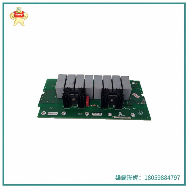
1336系列PCB板
部件编号 1336-SN-SP10A-74101-363-51
产品类型带有缓冲PCB的备件套件
兼容性1336 PLUS, PLUS II,力和冲击
产品生命周期状态:已停产/过时
Allen Bradley 1336-SN-SP10A已被制造商停产,但我们专门从事过时的部件,可能仍然可以供应剩余和/或翻新更换1336-SN-SP10A单元,而不是迁移。
1336-SN-SP10A-74101-363-51用于Allen-Bradley的1336可调频率交流驱动器。它特别兼容1336 Plus, Plus II,冲击和力驱动器。本产品为二级装配部件的备品备件。每个驱动器使用三(3)减震器套件。
1336-SN-SP10A-74101-363-51该缓冲器印刷电路板(PCB)用于帧E或输出功率为150、200、250和X300HP的驱动器。缓冲板安装在驱动器的主机箱内部,位于转换器舱内桥式散热器的一侧。
1336-SN-SP10A-74101-363-51当更换这个板时,电源必须从驱动器中取出,最好是锁定在访问之外。即使驱动器的电源被移除,也不要立即触摸组件,因为它具有短期存储电压的电容器。在继续之前,请测量驱动器的逆变器托架上的TB1端子座上的+DC和-DC。同时,请严格遵守静电防护措施,避免损坏其他固态设备。
要卸载缓冲板,请拆卸终止于+06和-16插接连接的引线。根据接线端子的出处正确地标记这些电线。卸载位于81、82和83端子的引线。相应地给电线贴上标签。从四(4)个塑料支架上卸下驱动器。安装新板,根据四(4)个孔对齐板,并将标记的引线终止到适当的插接连接。
Brand allen-bradley/Rockwell Automation
1336 series PCB board
Part No. 1336-SN-SP10A-74101-363-51
Product Type Spare parts kit with buffer PCB
Compatibility 1336 PLUS, PLUS II, force and impact
Product life cycle status: Discontinued/obsolete
Allen Bradley 1336-SN-SP10A has been discontinued by the manufacturer, but we specialize in obsolete parts and may still be able to supply surplus and/or retrofit replacement 1336-SN-SP10A units instead of migrating them.
1336-SN-SP10A-74101-363-51 for Allen-Bradley's 1336 adjustable frequency AC driver. It is particularly compatible with the 1336 Plus, Plus II, impact and force drives. This product is a spare part for secondary assembly parts. Each drive uses three (3) shock absorber kits.
1336-SN-SP10A-74101-363-51 This buffer printed circuit board (PCB) is used for frame E or drives with output power of 150, 200, 250 and X300HP. The buffer plate is mounted inside the driver's main case, on the side of the bridge radiator in the converter bay.
1336-SN-SP10A-74101-363-51 When replacing this board, the power supply must be removed from the drive, preferably locked out of access. Even if the power supply to the drive is removed, do not touch the component immediately because it has a capacitor that stores voltage for a short time. Before proceeding, measure the +DC and -DC on the TB1 terminal block on the driver's inverter carrier. At the same time, strictly observe the ESD preventive measures to avoid damage to other solid-state devices.
To unload the buffer board, remove the leads that terminate at the +06 and -16 pin connections. Mark the wires correctly according to the source of the terminals. Unload the leads at terminals 81, 82, and 83. Label the wires accordingly. Remove the drive from the four (4) plastic brackets. Install the new board, align the board according to the four (4) holes, and terminate the marked leads to the appropriate plug connection.
雄霸工控

微信二维码
Copyright © 2022-2024 厦门雄霸电子商务有限公司 版权所有 备案号:闽ICP备14012685号-33